طراحی سیستم های فاضلابی
| Product | InstalSystem 5 |
| Type of article | DESIGNING LESSON |
| Source for translation | 2022-06-06 |
محدوده درس
این مقاله، راه پایه طراحی یک سیستم فاضلابی داخل ساختمان ثقلی است. این سیستم از وسایل مصرف کننده شروع میشود و به نقطه خروجی فاضلاب ساختمان ختم میشود.
ماژول ها و ترکیب بندی نرم افزار
- InstalSystem 5 همراه با ماژول:
- سیستمهای ثقلی فاضلاب خانگی
فاز اولیه
پروژه شامل همه تنظیمات و پیش فرض های اولیه در فایل نمونه است. نقشه اولیه براساس یک فایل اتوکد گسترش پیدا کرده است.
گام هایی برای اقدام
باز کردن فایل پروژه
- وقتی یک طرح جدید را آغاز میکنید، یک فایل الگو را که از قبل تنظیمات لازم در آن انجام شده است را انتخاب کنید.
- یک فایل که شامل یک ساختار ساختمان را وارد کنید: حداقل اطلاعات شامل مختصات درست و همین طور ضخامت درست کف (اسلب) است. و یا همین طور شامل کنید سیستم فاضلابی را، اطلاعات و داده های اولیه لازم برای سیستم فاضلابی را از یک فایل الگو مناسب وارد کنید.
For more information, see: فایل های الگو
| Project files
|
Initial state, isproj Sewage installation, isproj |
| Designed with | InstalSystem 5 Rev. 23.B1 |
| Required modules | ماژول پایه سیستمهای ثقلی فاضلاب خانگی |
| Project range | Sewage installation |
| Used catalogues |
Standard water taps and whiteware |
| Type of building | residential building with basement 3-storey |
| Building structure | Base drawing all storeys, dwg |
| Drawings range | Plan view |
| Prepared by |  www.instalsoft.com |
| Legal disclaimer | The whole file or parts of the project may be copied |
| Calculation results | Results, pdf |
| Drawing results | Full printout, dwg Storage, pdf Ground floor, pdf Attic floor, pdf |
ویرایش داده های عمومی
فعال کنید: سیستمهای فاضلابی.
اطلاعاتی که را هندسه و طرح سیستم فاضلابی را به شدت تحت تاثیر قرار میدهد را برای هر پروژه جداگانه معین کنید.
- عمق پیش فرض نقطه خروجی فاضلاب به خارج (به صورت نسبی به سطح صفر). همینطور سطح زمین (ground level) را مد نظر داشته باشید.
- مشخصات ضخامت کف (لایه هایی که روی اسلب قرار میگیرند.) در طبقات مستقل. - توجه! این تغییرات ممکن است سیستمهای طراحی شده دیگر در این فایل را نیز تغییر دهد. همینطور مصرفکنندگان فاضلابی که روی کف و یا در ارتفاعی از پیش تعریف شده از کف تعریف شده اند را تحت تاثیر قرار می دهد.
تنظیمات بیشتری در دادههای عمومی ممکن است نیاز باشد، زمانی که کار با یک فایل آغاز شود که تنظیمات اولیه مربوط به ماژول فاضلابی در آن اعمال نشده است یا از یک فایل الگو استفاده نشده باشد. # در این برگه مشخص کنید سیستمهای فاضلابی:
- گزینهها و استانداردهاي محاسبه:
- در برگه استاندارد محاسبه آنچه برای بازار کاری خود مناسب است را انتخاب کنید.
- نوع ساختمان,
- حداقل شیب را با توجه به نیاز های طراحی خود و مقررات اعمالی انتخاب کنید.
- جهت پیش فرض را مشخص کنید برای روش اجرای شاخهها,
- For the selected direction define the default value of the فاصله از کف نقاط اتصال رایزر آنچه قابل به کار گیری است در تمام طبقات پروژه, وانچه که می تواند به طور مجزا در هر طبقه ویرایش شود.
- درصد پیش فرض پر شدگی لوله
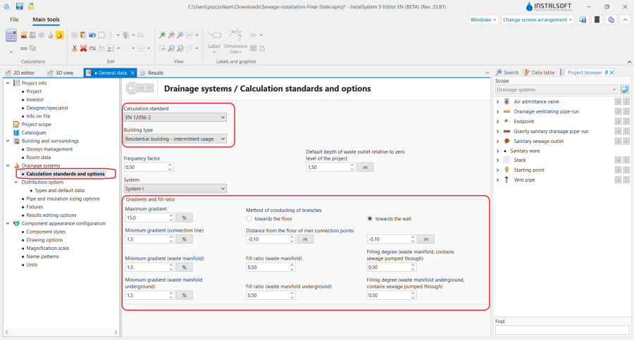
در تب گزینهها و استانداردهاي محاسبهمشخص کنید شیبها و نسبت پر شدگی.
- گزینهها و استانداردهاي محاسبه:

- In the سیستم توزیع tab specify انواع و دادههای پیش فرض for each component with regard to,
- نوع لوله پيش فرض: فاضلاب / ونت for the various pipe-run locations,
- روشهای پیش فرض اجرای اتصالات - the picklists depend on the content of default pipe catalogues for the given location,
- انواع پیش فرض: مولفه هاي ديگر.
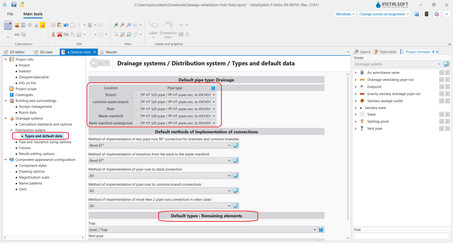
2.In the انواع و دادههای پیش فرض tab select نوع لوله پيش فرض: فاضلاب / ونت and change انواع پیش فرض: مولفه هاي ديگر.
- In the مصرفکنندهها table assign data with regard to:
- سیستمهای اتصال پیش فرض - from the pipe folder specified for the connections select the appropriate system for the given fixture type,
- سیستم اتصال سایر لوازم بهداشتی - common selection for the remianing fixture types.
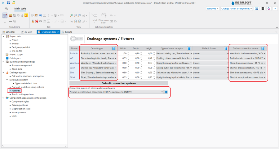
3.In the مصرفکنندهها tab specify قاب پیش فرض, سیستمهای اتصال پیش فرض, سیستم اتصال سایر لوازم بهداشتی.


- Editing data in the مدیریت طبقات project section
- For storeys with a drainage network, determine the required value of نقطه اتصال استک به منیفلد (جمع آوری), "Auto" means letting the program decide this depending on the location of the sewage outlet. By specifying a value manually, we can e.g. impose the location of the main sewer under the basement ceiling.
- روش اجرای شاخهها - change if on a given storey the value is different from that set out in the general data above,
- فاصله از کف نقاط اتصال رایزر - negative values mean placing junctions on risers in plumbing shafts within a floor or ceiling slab, which may be necessary to maintain proper gradients from low-placed fixture outlets.
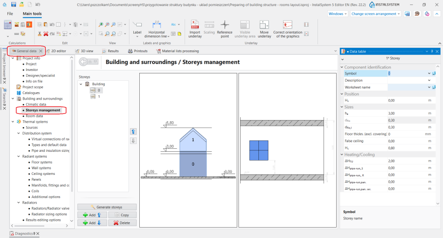
4.For each storey the فاصله از کف نقاط اتصال رایزر can be modified.

Editing the installation and its data
Editing the installation structure
- Insert sanitary appliances, if these were not included in the file, e.g. from a previously completed design of water supply system For more information, see: Editing sanitary installation.
- Insert استک elements and complete their essential data in the جدول دادهها window:
- Depending on the purpose of the استک element, declare the proper type in the انواع خط لوله field.
- In the المان در بالای استک field, defie the way in which the pipe-run at the last storey for the استک element finishes:
- For the waste stack, it is necessary to choose the vent element (e.g. لوله ونت), leaving the هیچکدام option selected means that a vent manifold should be added in future,
- The vent استک should be ended with a vent element, or it should be connected to the drainage stack.
- In the موقعيت section, declare the range of storeys of the element.
- Define additional parameters for double stacks (فاضلاب بهداشتی + ونت): فاصله محور لولهها, ایجاد خودکار ونت موازی checkbox selection.
- For theاستک elements with bypass ventilation (with selected checkbox ایجاد خودکار ونت موازی in the جدول دادهها element window), verify and, if needed, change the following parameters:
- Select the اتصال میانی خودکار ونت استک و استک فاضلاب در هر طبقه checkbox,
- Set the value in the فاصله اتصالات میانی ونت از سقف field,
- Change the value in the ارتفاع اتصال پایینی ونت استک به استک فاضلاب field,
- (Optional) declare a number > 0 in the تعداد طبقات با استک اضافی field (counting from the lowest storey).
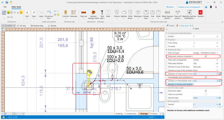
5. ایجاد خودکار ونت موازی.
- Insert the خروجی فاضلاب بهداشتی and verify its position in the model,
- Connect the appliances with the استک using the خط لوله components. ATTENTION! In the drainage system this component always consists of a single section. If, for perpendicular connections, other than 90-degree branch fittings are needed, they should be declared in the اطلاعات كلي window in the انواع و دادههای پیش فرض tab in the روشهای پیش فرض اجرای اتصالات section, and connections of خط لوله فاضلاب بهداشتی ثقلی elements should be drawn as perpendicular (do not use "chamfering" in the plan view).
- On the storey where خروجی فاضلاب بهداشتی is placed, connect it with the استک, to form the collector sewer. The collector sewer elevation is by default adjusted to the posion of the خروجی فاضلاب بهداشتی, unless the value of نقطه اتصال استک به منیفلد (جمع آوری) has been specified manually.

Verifying the correctness of the installation structure.
- Verify the connectness of the connections of the installation components using the بررسی اتصالات function (Shortcut: Shift + F2). ATTENTION! For some types of appliances where the approach direction should be perpendicular to the object (e.g. toilet with a tail outlet), this function automatically creates short pipe-runs immediately next to the appliance to ensure this perpendicularity.
- Verify the correctness of the installation structure and detect collisions with other systems using the نمای 3 بعدی, if necessary, enabling the view of other editing ranges, it is advisable to turn off the display of walls.
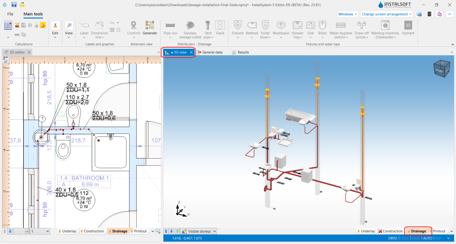
6. Verifying the correctness of the drainage installation structure using the نمای 3 بعدی. - Verify provisionally the vertical routing of pipe-runs in the model (calculations may alter this).
- Specify, if necessary: the elevations of the ends of the pipe-runs (paying attention to constraints resulting from their connection to other components), the actual gradients of pipe-runs.

ATTENTION! Following such changes, verification must be repeated.
Editing installation components data
- Verify and adjust the drainage-specific data of the appliances (DU, outlet diameter)
- If necessary, verify and adjust pipe-run data other than the default (pipe type, diameter setting, location)
- (Optional) If needed, change the way of realizing chosen pipe-run nodes into another than the default one. It is possible to change it in the جدول دادهها window for the اتصال element.
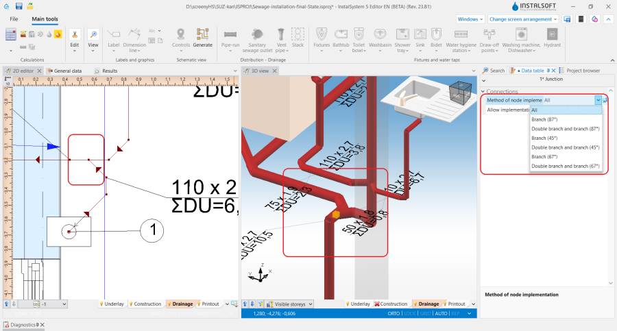
7. Change of pipe-run node realization.

Running the calculations
- If no errors are found during verification, start the calculation of the سیستمهای فاضلابی by clicking
 in the محاسبات section of the toolbar. The calculations finally determine the vertical routing of the pipe-runs.
 - After the calculations, it is possible to correct manually the vertical passage of pipe-runs in the following way:
- imposing proper values in the جدول دادهها window for the خط لوله فاضلاب بهداشتی ثقلی element in the following fields: شیب واقعی, ارتفاع گره اول, ارتفاع گره دوم.
- dividing the chosen elements of خط لوله فاضلاب بهداشتی ثقلی in parts and properly modifying their data.
It is recommended to implement such changes gradually and to observe their influence upon the system, as the change in one node after calclations may have a significant impact on teh positioning of its greater part.
- Attention Defining the vertical passage of pipe-runs, the program does not exceed the value imposed in the حداکثر گرادیان field in the اطلاعات كلي window in the گزینهها و استانداردهاي محاسبه tab. This value is also automatically propagated to data of all the خط لوله فاضلاب بهداشتی ثقلی elements. In case a difference of ordinates between the end of the calculated pipe-run and another pipe-run or a sewage outlet occurs, an additional vertical pipe-run is generated. An alternative solution of this issue is to allow posing pipe-runs with a greater gradient, by augmenting individually for each pipe-run a new value in the حداکثر گرادیان field in the اطلاعات كلي window and by recalculating the project.

Verification of results
- After calculations, the system layout should be verified visually by means of the نمای 3 بعدی.
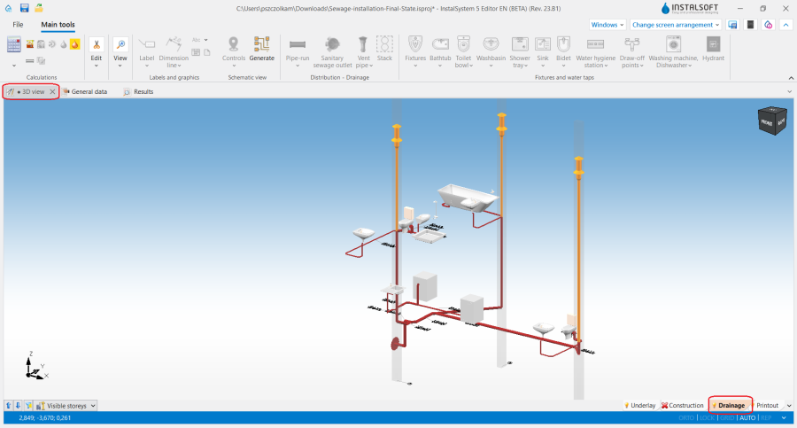
8. Visual verification of pipe routing using the نمای 3 بعدی function. - The dimensioned diameters of the pipe-runs and fittings can be verified directly in the drawings
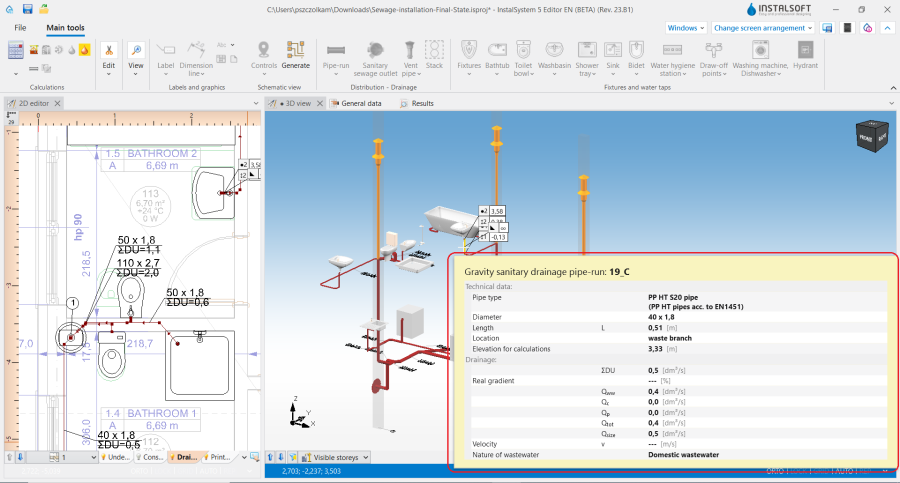
9. Verification of the dimensioned pipe-run diameters using the pipe-run properties window. - (Optional) If a catalogue with visualisation of fittings in nodes is used in the project, it can be used in order to assess correctness of fittings dimensioning for pipe-run nodes. To do so, node visualisation should be turned on in the نمایش اتصالات فاضلاب (BETA) for در نقشه نمای پلان and در نمای 3 بعدی in the اطلاعات كلي window in the گزینههای طراحی tab.
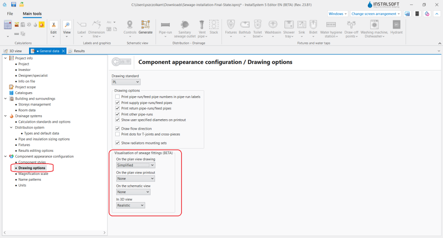
10. Ustawienia wizualizacji kształtek.
Attention! Only nodes with correctly chosen fittings, that is to say nodes without warning messages in the عیبیابی window.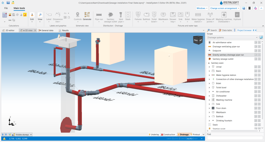
11. presentation of dimensioned fittings in the نمای 3 بعدی window. - Other forms of presentation of calculation results are component labels and tables of results For more information, see: Presentation of the calculations result
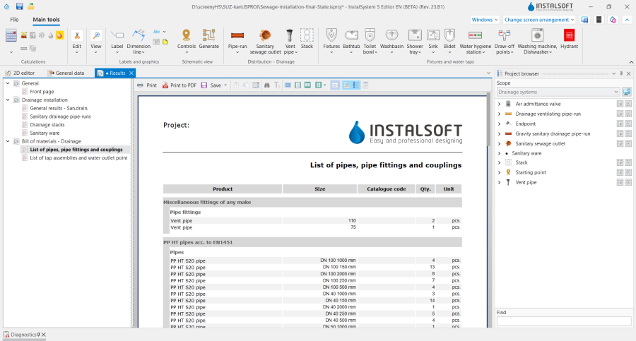
12. ليست لولهها، اتصالات و كوپلينگها.


Generating schematic views
The schematic view will be generated automatically as described For more information, see: Automatically generate schematic views
Preparing drawings for export/printing
- To have the results for pipe-runs and installation nodes included in the printout, labels must be inserted For more information, see: Preparation of drawings for export / printing
- Completed drawings can be printed and/or exported For more information, see: Export / print results and drawings