شروع کار با InstalSystem 5: تفاوت میان نسخهها
بدون خلاصۀ ویرایش |
بدون خلاصۀ ویرایش |
||
| خط ۸۷: | خط ۸۷: | ||
* به طور خاص وارد کرد و ویرایش اطلاعات در این نسخه بسیار سرراست و خالی از اشکال است. ارگونومیک بودن و راحتی محاسبات و ویرایش طراحی یک از اصلیترین ویژگیهای محیط کاری '''SuperpipeCAD 5''' است. | * به طور خاص وارد کرد و ویرایش اطلاعات در این نسخه بسیار سرراست و خالی از اشکال است. ارگونومیک بودن و راحتی محاسبات و ویرایش طراحی یک از اصلیترین ویژگیهای محیط کاری '''SuperpipeCAD 5''' است. | ||
* نرم افزار به طور خودکار مختصات افقی خطوط رو را براساس جانمایی وسایل مصرفی تعیین میکند. علاوه بر این استفاده کننده میتواند ارتفاع خطوط لوله (مختصات عمودی) را با استفاده از جدول دادهها تعیین کند. اعمال این تغییرات با انجام عملکرد "چک کردن اتصالات" انجام خواهد شد. چک کردن اتصالات همواره اولین گام انجام محاسبات است. <br/> | * نرم افزار به طور خودکار مختصات افقی خطوط رو را براساس جانمایی وسایل مصرفی تعیین میکند. علاوه بر این استفاده کننده میتواند ارتفاع خطوط لوله (مختصات عمودی) را با استفاده از جدول دادهها تعیین کند. اعمال این تغییرات با انجام عملکرد "چک کردن اتصالات" انجام خواهد شد. چک کردن اتصالات همواره اولین گام انجام محاسبات است. <br/> | ||
مثال | مثال هایی از ویرایش سیستم ها در ویدیوهای زیر موجود است. | ||
<br/>{{#ev:youtube|wonqVv7UXf4|900||||rel=0}} <br clear="all"/> | <br/>{{#ev:youtube|wonqVv7UXf4|900||||rel=0}} <br clear="all"/> | ||
<br/>{{#ev:youtube|hTwbglymv4M|900||||rel=0}} <br clear="all"/> | <br/>{{#ev:youtube|hTwbglymv4M|900||||rel=0}} <br clear="all"/> | ||
<br/>{{#ev:youtube|b9OkGJMtFCM|900||||rel=0}} <br clear="all"/> | <br/>{{#ev:youtube|b9OkGJMtFCM|900||||rel=0}} <br clear="all"/> | ||
''' | ''' اطلاعات جزیی تر در ارتباط با " ویرایش سیستمهای تاسیساتی" با توجه به نوع سیستمی که طراحی میشود یا محاسبات آن انجام میشود. در قسمت مربوط به توضیحات عملکردهای نرم افزار آمده است.''' - see: [[InstalSystem 5|DESIGN APPLICATIONS]] | ||
==== | ==== سنجش درستی ساختار سیستم های تاسیساتی ==== | ||
قبل از وارد کردن جزییات مربوط به اجزا، ایده خوبی است که ساختار کلی سیستم تاسیساتی ایجاد شده را بررسی کنیم. برخی اصلاحاتی که باید اعمال شوند ممکن است باعث تغییر برخی اجزا یا اساسا حذف آنها شود لذا زمان لازم برای وارد کردن جزییات در این اجزا هدر میرود. ابزارهای زیر برای انجام اینکار در دسترس هستند: | |||
# | # ابزاری که برای چک کردن اتصالات بین اجزا به کار میرود، این است ''<IS_TS id=btCheckFlow/>'' ابزاری که همچنین از طریق کلید میانبر Shift + F2 از صفحه کلید نیز در دسترس است.<br/>[[File:Check-connections.png|900 px|RIGHT|thumb|5. "Check connections" function]]<br clear="all"/><br> | ||
# The tool that enables visual verification of the installation structure is, as is the case with building structure verification, the ''<IS_TS id=View3D/>''. The ''<IS_TS id=View3D/>'' can be enabled permanently, which allows verifying system correctness continuously during editing. In this case it is particularly advantageous to work using two display monitors simultaneously. Note, however, that using ''<IS_TS id=View3D/>'' slows down the program. When working on a slow computer or working with a large project, it is better to enable ''<IS_TS id=View3D/>'' only to verify the status of the project, and to do the design work without opening the ''<IS_TS id=View3D/>'' window.<br/>[[File:Instalation-project.png|900 px|left|thumb|6. Installation structure]]<br clear="all"/> | # The tool that enables visual verification of the installation structure is, as is the case with building structure verification, the ''<IS_TS id=View3D/>''. The ''<IS_TS id=View3D/>'' can be enabled permanently, which allows verifying system correctness continuously during editing. In this case it is particularly advantageous to work using two display monitors simultaneously. Note, however, that using ''<IS_TS id=View3D/>'' slows down the program. When working on a slow computer or working with a large project, it is better to enable ''<IS_TS id=View3D/>'' only to verify the status of the project, and to do the design work without opening the ''<IS_TS id=View3D/>'' window.<br/>[[File:Instalation-project.png|900 px|left|thumb|6. Installation structure]]<br clear="all"/> | ||
نسخهٔ ۴ ژوئیهٔ ۲۰۲۲، ساعت ۱۰:۴۶
| محصول | superpipeCAD_5 |
| نوع مقاله | درسنامه های طراحی |
| منبع ترجمه | 2022-02-23 |
محدوده درس
این مقاله اطلاعات عمومی را در ارتباط با محیط کاری SuperpipeCAD_5 ارایه میکند و گامهای اولیه در طراحی را توصیف میکند. بسته نرم افزاری شامل یک "مدیر برنامه" و یک "ویرایشگر" است. به طور همزمان فقط یک مدیر اما چند ویرایشگر باز می توانند باز باشند.
به همین دلیل ذخیره کردن فایل ها برخلاف باز کردن آنها فقط با ویرایشگر مجاز است. همه قابلیت های نرم افزار تنها در یک ویرایشگر قابل دسترسی است. برخلاف ورژن 4 که چند ماژول نرم افزاری ارایه شده بود.
ماژول ها و ترکیب بندی نرم افزار
- ورژن 5 نرم افزار superpipeCAD .
- اتصال اینترنت
وبینارها
We encourage you to see the video from our webinars on the topics described in this article:
The webinars present the topics described in this article, but they aren’t a recording of this lesson.
گام های اقدامی
آماده سازی محیط کاری
بدست آوردن دسترسی به نرم افزار
در ابتدا لازم است به فایل های نصب نرم افزار دسترسی پیدا کنید. این فایل ها را می توانید از این لینک دانلود کنید: Installation files.
نصب، فعالسازی و به روز رسانی
بعد از دانلود فایل ها، باید آن ها را روی دستگاه خود ذخیره کرده و با استفاده از گزینه "نصب" شروع به نصب نرم افزار کنید.

نرم افزار نیازمند نصب روی کامپیوتر و فعالسازی است. برای فعالسازی نرم افزار نیاز به یک کد درست است. نسخه آزمایشی احتیاج به کد ندارد. نسخه های آزمایشی را می توانید از لینک زیر دانلود کنید:Trial versions.

قبل از نصب، از اینکه کامپیوتر شما مشخصات لازم (لینک زیر) را دارد، اطمینان حاصل کنید:
Package technical specifications.
For more information, see: Installation, activation and update InstalSystem 5 package.
بازکردن فایل پروژه و مدیریت پروژه ها
ساخت یک پروژه جدید و بازکردن یک پروژه موجود
نرم افزار را به کار بیندازید، برای این کار منوی استارت را باز کنید، نسخه 5 را بیابید و روی "مدیریت نرم افزار" ورژن 5 کلیک کنید.
- پروژه جديد وقتی که یک فایل جدید را باز می کنید، میتوانید یک فایل الگو را برای استفاده در نرم افزار انتخاب کرده و نسخه دلخواه را برای ادامه کار بر گزینید. توصیه میشود آخربن نسخه نرمافزار را انتخاب کنید.
- باز كردن پروژه برای باز کردن یک فایل موجود، میتوانید نسخه مورد نظر خود را برای ادامه ویرایش فایل انتخاب کنید. این گزینه شما را قادر میسازد تا ادامه ویرایش فایل را با همان نسخه ای از نرمافزار ادامه دهید که فایل در ابتدا با آن ساخته شده است. superpipeCAD ورژن 5 می تواند فایل های ورژن 4 را نیز بخواند.
InstalSystem 4.
For more information, see: Design based on a project file from InstalSystem 4

مدیریت فایل های پروژه
جزییات را می توانید در این لینک ببینید: Project and application management
کارکردن با پروژه
اطلاعات کلی
در اولین مرحله کار کردن با پروژه، اطلاعات کلی تعیین و تنظیمات پیش فرض که در طول پروژه استفاده میشوند، مشخص می شوند. br/>الگو:For more information, see: General data>
المان های اساسی محیط ویرایشگر گرافیکی
جای اساسی که پروژه در آن ویرایش می شوند این پنجره ها هستند: ویرایشگر 2 بعدی و جدول دادهها. چگونگی تغییر این پنجره ها در تصویر در اینجا توضیح داده شده: Software configuration. مهم ترین عملکردها از این طریق قابل دستیابی هستند: ابزارهای اصلی از طریق نوار ابزار و همچنین منوی آشکار شدنی بعد از فشردن کلیک راست موس. منوی آشکار شدنی وابسته به محتواست. قابلیت دسترسی و محتوای آن بستگی دارد به مکان آن در تصویر و یا آنچه نمایش داده می شود.

تغییر در ساخت نرم افزار
SuperpipeCAD نسخه 5 ممکن است ساخت و شکل های مختلفی را در سطوح مختلف داشته باشد. تا بتواند قابلیت های لازم را در اختیار استفاده کننده نهایی قرار دهد. For more information, see: Software configuration.
تنظیم ساختار ساختمان
ساختار ساختمان پایه ای را تشکیل می دهد که طراحی سیستم روی آن انجام میشود. ساختمان ممکن است طبقات زیادی داشته باشد. یک شیت جدا به صورت نمای پلن به طور اتوماتیک برای هر طبقه ساخته میشود. در این شیت، المان های ساختار ساختمان و سیستم تحت طراحی در آن شیت، قابل ویرایش هستند. حیطه مختلف پروژه در برگهها (لایه ها)ی مختلف قابل ویرایش هستند. این در حالی است که کل ساختمان و سیستم های آن یک پروژه واحد را تشکیل میدهند.روشهای گوناگونی برای آمادهسازی ساختار ساختمان برای طراحی وجود دارد. انتخاب این روشها بستگی به ساختار ساختمان در دسترس و منبع اطلاعاتی موجود دارد. و بیش از این بستگی دارد به محدوده کاری پروژه که مد نظر است. بنابراین شما ممکن است ساختار یک ساختمان به اشکال زیر تعریف کنید:
- "چیدمان اتاق ها (یا فضاها)" زمانی که فقط اتاق ها یا فضا ها حائز اهمیت هستند.
- "کل ساختار ساختمان" شامل دیوارها، درها و پنجره ها، سقف و غیره.
For more information, see: Preparation of building structure
For more information, see: Import underlay files
سنجش درستی ساختار ساختمان
For more information, see: Verification of the correctness of building structure
For more information, see: view navigation in the graphical editor
ویرایش سیستم های تاسیساتی
راه اساسی برای ورود اطلاعات به نرم افزار superpipeCAD 5 ویرایش در محیط گرافیکی نرم افزار است. طراحی شامل جانمایی موارد تاسیساتی در نقشه و برقرای اتصال مناسب بین آنها است. انجام اینکار روی نمای پلن طبقات خواهد بود. سیستم های تاسیساتی کار شده بعدا میتوانند به اشکال مختلف ویرایش شوند. همچنین میتوان قسمتهایی از طرح را کپی و در جای دیگر الصاق کرد و سپس ویرایشهای دیگر را روی آن انجام داد.
- بسته نرم افزاری عملکردهای مختلفی را ارایه میکند که میتواند ویرایش گرافیکی را ساده تر کند و زمان لازم برای انجام امور دستی را کاهش دهد. برخی از اجزا ممکن است به طور اتوماتیک وارد یا ساخته شوند. همینطور این امکان وجود دارد که اجزای تاسیساتی به صورت گروهی وارد شوند.
- دسته ای از اجزای تاسیساتی از پیش تعریف شده وجود دارند که می توان از آن ها استفاده کرد بعنوان مثال: 'ترسيم جدول', که داده های طراحی میتوانند وارد شوند و میتوان هنگام پرینت از آنها استفاده کرد. یا اجزای تعاملی مثل 'جدول كلكتور' و برچسب. بعد از اختصاص آن ها به اجزا، این المان ها اطلاعات مربوطه را به طور خودکار نمایش می دهند.
- به طور خاص وارد کرد و ویرایش اطلاعات در این نسخه بسیار سرراست و خالی از اشکال است. ارگونومیک بودن و راحتی محاسبات و ویرایش طراحی یک از اصلیترین ویژگیهای محیط کاری SuperpipeCAD 5 است.
- نرم افزار به طور خودکار مختصات افقی خطوط رو را براساس جانمایی وسایل مصرفی تعیین میکند. علاوه بر این استفاده کننده میتواند ارتفاع خطوط لوله (مختصات عمودی) را با استفاده از جدول دادهها تعیین کند. اعمال این تغییرات با انجام عملکرد "چک کردن اتصالات" انجام خواهد شد. چک کردن اتصالات همواره اولین گام انجام محاسبات است.
مثال هایی از ویرایش سیستم ها در ویدیوهای زیر موجود است.
اطلاعات جزیی تر در ارتباط با " ویرایش سیستمهای تاسیساتی" با توجه به نوع سیستمی که طراحی میشود یا محاسبات آن انجام میشود. در قسمت مربوط به توضیحات عملکردهای نرم افزار آمده است. - see: DESIGN APPLICATIONS
سنجش درستی ساختار سیستم های تاسیساتی
قبل از وارد کردن جزییات مربوط به اجزا، ایده خوبی است که ساختار کلی سیستم تاسیساتی ایجاد شده را بررسی کنیم. برخی اصلاحاتی که باید اعمال شوند ممکن است باعث تغییر برخی اجزا یا اساسا حذف آنها شود لذا زمان لازم برای وارد کردن جزییات در این اجزا هدر میرود. ابزارهای زیر برای انجام اینکار در دسترس هستند:
- ابزاری که برای چک کردن اتصالات بین اجزا به کار میرود، این است بررسی اتصالات ابزاری که همچنین از طریق کلید میانبر Shift + F2 از صفحه کلید نیز در دسترس است.
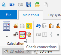
5. "Check connections" function - The tool that enables visual verification of the installation structure is, as is the case with building structure verification, the نمای 3 بعدی. The نمای 3 بعدی can be enabled permanently, which allows verifying system correctness continuously during editing. In this case it is particularly advantageous to work using two display monitors simultaneously. Note, however, that using نمای 3 بعدی slows down the program. When working on a slow computer or working with a large project, it is better to enable نمای 3 بعدی only to verify the status of the project, and to do the design work without opening the نمای 3 بعدی window.

6. Installation structure


Component data edit
Every component in the project has its set of data. Editing these data is possible in the جدول دادهها after marking that component. The جدول دادهها can be toggled on/off by selecting it in the پنجرهها menu on the toolbar or using the F12 key.

- A significant portion of the data of new components placed in the drawing is appended automatically. This highly facilitates work on the project. The range of automatically appended data differs depending on the type of component and on other factors.
- The basic mechanism in this area is propagation of General data
- Some data are established based on component location and size / shape of component placed in the drawing
- Many detailed data of components that are associated with catalogue data and have a specified catalogue type are read from the catalogue.
- Any default data can be overwritten with other data at any time. Information on whether the current value is derived from the or is another type of default data, or whether it is a user-defined value, is in the form of an icon placed to the right of the data field in the جدول دادهها. Clicking this symbol changes the data status. In particular it enables reverting to the Default status.
- A Computer symbol indicates a default value

- A Pencil symbol indicates a user-specified value

- A Computer symbol indicates a default value
- Data of any component can be entered or modified at any moment when working with the project.
- Component data can be edited right after placing the component in the project, and this is recommended for some components. This particularly applies to these components that do not depend on other drawing components and the number of which in the project is low.
- In the case of components the number of which is high it is advisable to edit their data at one stage to take advantage of group editing. To this end it is necessary to press and hold the Ctrl key and click every component to be marked or use the tools for multiple selection of elements. For more information, see: Selecting and editing multiple elements
Calculations and diagnostics
Calculations include all operations necessary to obtain complete results: data propagation, component sizing, engineering calculations and automatic graphical editing. All data that have an effect on the selected scope of the project are taken into consideration: general data, building data, drawings of the system under design, parameters of components used to construct the system taken from catalogues. This means that the program automatically provides high level of completeness and consistency of data and results. This approach greatly facilitates reverting to any of the previous stages of editing - after changing selected data, calculations can be conducted again to obtain complete and current results. Ease of reverting provides great comfort and speed of work in the context of calculating various design options, taking into account the changing requirements of the project developer or changes in the structure of the building introduced during the design of the installation.
Running calculations - the محاسبات section of the ابزارهای اصلی bar contains tools that enable starting and managing calculations. Calculations can be made for for all selected project scopes, in the depicted order (downwards), or for selected scopes. Calculation modules have been indicated with the red frame.

In the Calculations section of the Main tools toolbar, the following icons are present:
- Generate walls and slabs from rooms and building contour.For more information, see: Manual editing of rooms and automatic identification of walls and slabs on an underlay
- Check connections. For more information, see: Verification of the correctness of building structure
- Interactive radiant systems calculations.For more information, see: Interactive radiant systems calculations
Diagnostics and error list - Viewing and handling diagnostic messages
نتایج - Presentation of the calculations result
Preparation of drawings for export/printing
For more information, see: Preparation of drawings for export / import
Export/print results and drawings
Result tables and drawings can easily be printed or exported in one of the many available formats. In order to obtain printouts of drawings with results or of results tables as well as their export, it is necessary to enable proper program windows: "2D editor", "3D view", "Printouts" and to perform further actions in these windows.
- Print tables and lists - it is possible to create and save your own printouts and print results of calculations directly on the printing device or export to selected format.
- Print drawings - it is possible to determine the layout of graphic print pages and print drawings from project directly on the printing device or export to selected format.
For more information, see: Export / Print results and drawings.